Demo Video:
Source Code:
https://github.com/scottjgibson/rcBabyKart
Beginnings:
It all started when I found a “Power wheels” style toy at a thrift shop for $20. As you can see I’m a little excited about it.

It wasn’t working when I bought it as there were wiring issues and a bad battery. This wasn’t too much of a concern to me because I planned to overhaul it anyways.
It also started out as an Audi; being a BMW guy I figured I would change that too.
I ended up implementing the following features; I have some more things in mind, but it was just nice to get it working.
Features:
- Remote Control
- Throttle Control (not just on/off)
- Power Steering
- Lights
- “Turbo Mode”
Electronics Overview:
I decided to do the remote control right I should have a microcontroller in the car; this allowed me to add features like proportional steering, a turbo timer and eventually sound effects.
I used a standard RC transmitter/receiver set but interfaced the output of the receiver to an Arduino microcontroller. The RC Receiver outputs a pulsed signal for each channel. The length of the pulse corresponds to the position of the stick on the remote.
Hardware:

Battery:
I moved from a 6V 5AH battery to a 12V 7AH battery, it fit nicely in the under seat compartment. It also has the benefit of doubling the top speed!
Motors:
The drive motor is the same 6V motor which came with the car; I’m now running it using PWM so I keep an average of a 50% duty cycle in order to keep the motor from over heating. There is a “turbo” mode which gives the full 12V to the motor for a boost; it is timed and there is a forced cool down period which ensures the motor won’t burn out too soon.
The steering motor is a gear motor assembly attached to the steering column. I run it at a maximum 50% duty cycle; and the software manages a duty cycle between 20% and 50% depending on how far away the desired wheel position is from the set wheel position.
H-Bridge:
The H-Bridge is responsible for controlling the drive motor and steering motor. I used a cheap off the shelf dual channel H-bridge from aliexpress; its proven to work very well. It has PWM and direction inputs which are sent from the microcontroller. The only modification I had to do to it was solder some pull down resistors on the PWM pins; this was needed because when the microcontroller goes into reset the pins are in a high-impedance state which caused some erratic motion.

Wheel Position Feedback:
I looked at various methods to sense the wheel position. I ended up with something fairly low-tech; I attached a slider style potentiometer to the steering linkage. The slider doesn’t have to slide to its extents as the wheel input is calibrated as part of the calibration routine. The wiper of the potentiometer is connected to the analog input on the microcontroller.

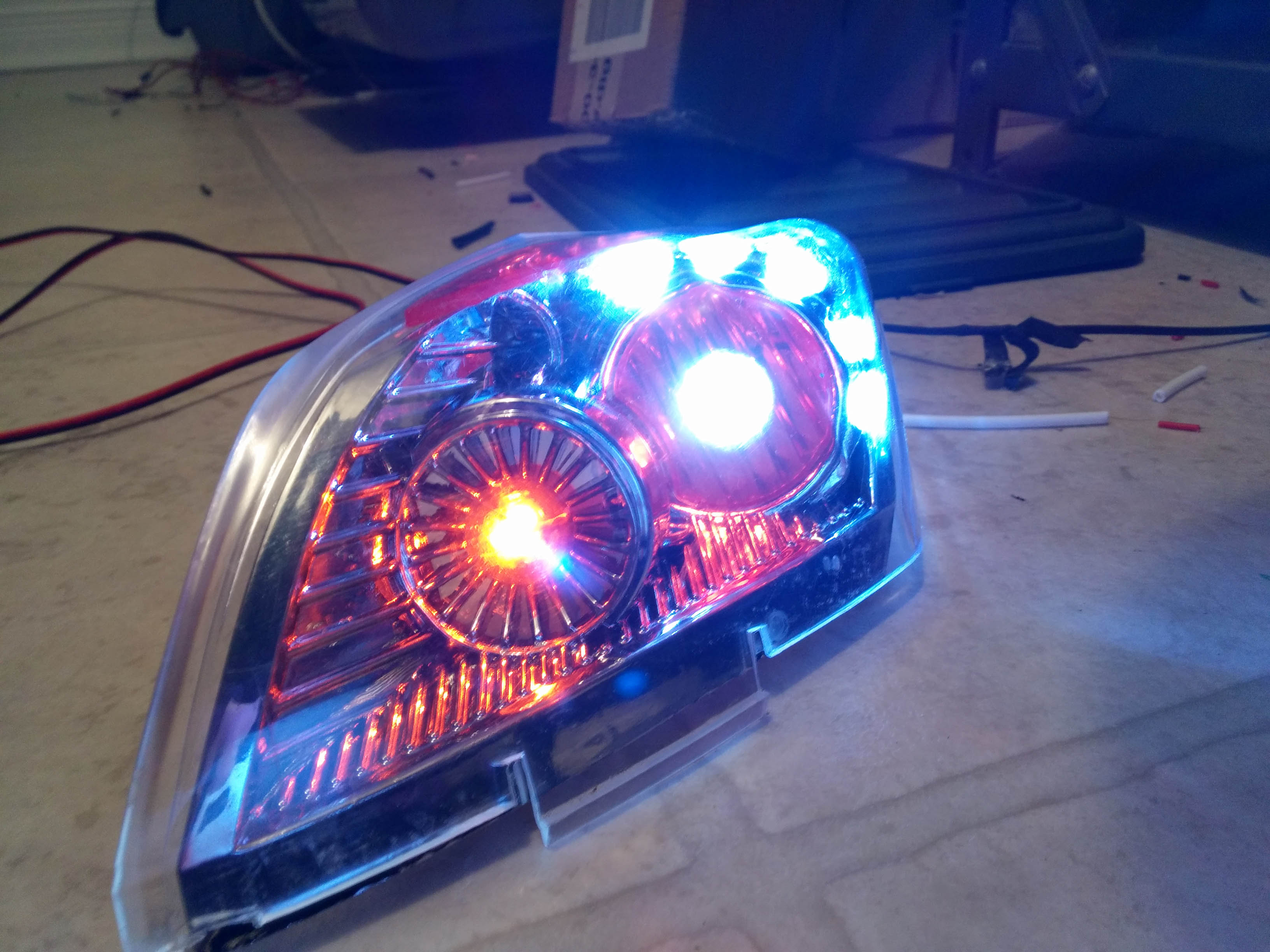
Lights:
I modified the existing headlights with lots of LEDs. I also added red LED light strips on the bottom. Again I just used whatever I had on hand; but it turned out pretty good. To control the LEDs I used a handy mosfet switch board I designed for another project. Its a simple breakout board which allows the mosfets to be used as a “low-side” switch. The circuit boards / diagrams are available here:
https://github.com/scottjgibson/4ch_mosfet_switch


Software:
The software is open source and freely usable: https://github.com/scottjgibson/rcBabyKart . I cleaned/packaged up a library which can be used for interfacing with the RC Receiver here: https://github.com/scottjgibson/RCArduinoFastLib
Calibration:
I wrote a calibration routine in order to calibrate the inputs from the RC Receiver as well as the input from the wheel position potentiometer. When you boot up the car while holding the “turbo” button it enters the calibration routine. During this time you move the joysticks on the RC Transmitter to their extent, and move the wheels to their extents. The calibration is stored in EEPROM so that you don’t have to do it every time.
Running:
Once the calibration is complete the system operates in one of two modes based on a hidden switch.
If the switch is in manual mode; the RC receiver is not needed and throttle is the only thing controlled. Its controlled based on two things; (1) the gas pedal switch, and the turbo button. When the throttle switch is pressed the motor is driven at a 50% duty cycle (6V), if the turbo button is pressed it is driven at a 100% duty cycle (12V). After the turbo timer expires (3 seconds right now) the motor goes into a cooldown state where it can’t go into turbo mode again for another (3 seconds).
If the switch is in “RC” mode the input from the RC receiver is used to drive the car. The only local input is the gas pedal switch. The gas pedal switch is there to ensure the driver is present and willing 🙂 The throttle control in RC mode is based off the input from the RC receiver; if above 50% joystick position it goes forward, below it goes back.
Steering is “closed-loop” in that it senses the current wheel position and compares it to the set wheel position from the RC Receiver. As the difference between the set and current wheel position increases the duty cycle of the steering motor increases to bring the wheels back in position. I added a “dead band” to the servo mechanism which allows for a defined amount of error between the current wheel position and set wheel position to prevent the motor from always working to set a very exact position.
Future Expansion:
I have a bit more that I am in the progress of adding.
Sound Playback:
I have purchased a embedded sound module ( WTV020-SD-16P). This will allow me to play back sounds based on what the car is doing. I’m planning on adding sound effects for startup (engine starting sound), acceleration and breaking sounds, and some buttons for fun sound effects.
Water Gun:
I have a windshield washer pump and spray nozzles from an old car; I’m planning on adding them on the front so you can spray people by pressing a button. I havn’t added it yet because I figure I will be the person being sprayed…
Fuel Gauge:
I also plan to add a “fuel gauge” ie. battery meter to keep track of how much charge is remaining.

Pingback: Homemade Remote Controlled Kids Car #makereducation « adafruit industries blog
Needing some assistance with the h bridge you have pictured here. Please contact me if you can.
using this code just to test signal prior to connecting motors but most of the time, I get fluctuating dc voltages on the motor1 and 2 terminal screws.
int pwm2Pin = 3;
int pwm1Pin = 2;
int ledPin = 13;
int dir2Pin = 24;
int dir1Pin = 22;
int ledState = LOW;
void setup(){
pinMode(13, OUTPUT);
pinMode(pwm1Pin, OUTPUT);
pinMode(pwm2Pin, OUTPUT);
pinMode(dir1Pin, OUTPUT);
pinMode(dir2Pin, OUTPUT);
}
void loop(){
digitalWrite(13, HIGH);
delay(1000);
digitalWrite(13, LOW);
delay(1000);
digitalWrite(dir1Pin, LOW);
digitalWrite(dir2Pin, LOW);
analogWrite(pwm1Pin, 170);
analogWrite(pwm2Pin, 170);
}
LikeLike